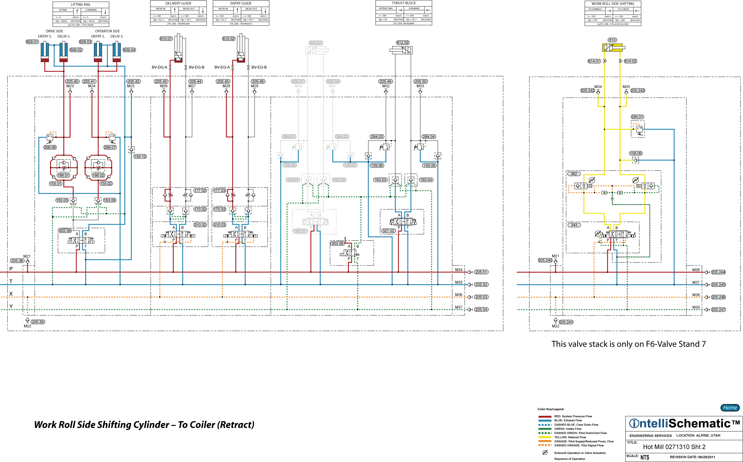
Event: Work Roll Side Shifting Cylinder - To Coiler (Retract)
For previous sequences in this event see the event “Roll Change HPU – On.”
Note that this event describes the sequences for Mill Stand F1. The same sequences apply for stand F2 through F6, though the component numbers will change. Refer to the relevant schematic for each stand for the appropriate component number.
1) Proportional Directional Control Valve 343 is energized to the crossover flow pattern allowing pressurized hydraulic fluid to flow through the valve passing from P to B. Next, the fluid flows through the B-side of Pressure Compensator Valve Module 382 which provides a constant flow rate regardless of the load on the cylinder. Then the fluid flows into the rod end of Side Shifting Work Roll Cylinder 613 causing the cylinder to retract. The proportional directional control valve controls the retraction speed of the cylinder using both meter-in and meter-out flow control.
2) Exhaust fluid from the cap end of the cylinder flows through the A-side of Pressure Compensator Valve Module 382, then back to tank through the proportional directional control valve, passing from A to T, Check Valve 122.01 and Duplex Return Line Filter 045.01.
3) Note that Pressure Relief Valve 285.01 protects the cap end of the cylinder from overpressure caused by external loads acting to retract the cylinder rod. Check Valve 158.06 provides makeup fluid to the rod end of the cylinder to prevent cavitation in the event this action occurs.

