|
|
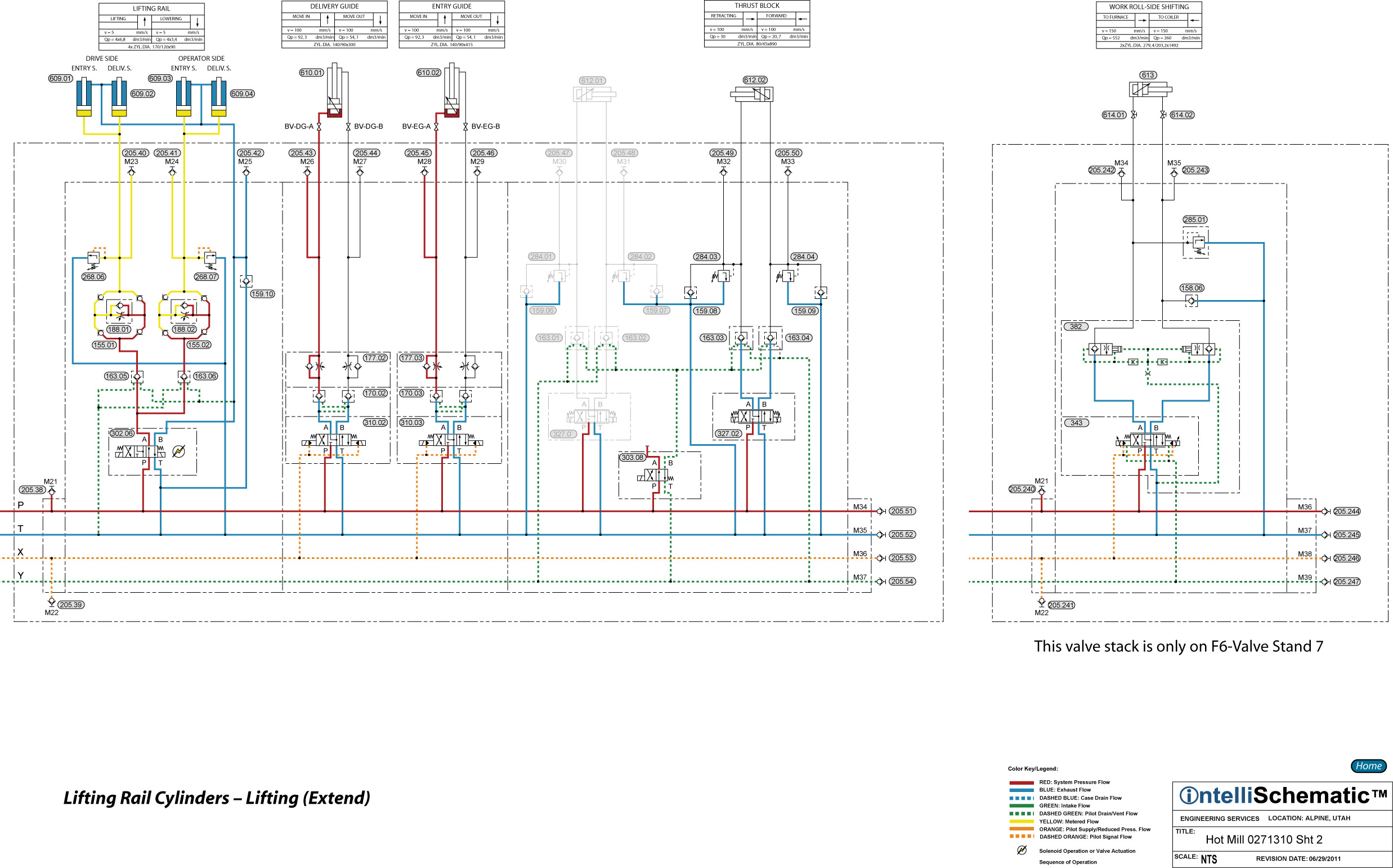
Lifting Rail Cylinders - Lifting (Extend) |

For previous sequences in this event see the event “Roll Change HPU – On.”
Note that this event describes the sequences for Mill Stand F1. The same sequences apply for stand F2 through F6, though the component numbers will change. Refer to the relevant schematic for each stand for the appropriate component number.
1) Directional Control Valve 302.06 is energized to the parallel flow pattern allowing pressurized hydraulic fluid to flow through the valve, passing from P to A. The fluid then divides and flows freely through Pilot Operated Check Valves 163.05 and 163.06.
2) The fluid which flowed through PO Check Valve 163.05 then flows through Rectifier Plate 155.01 and Pressure Compensated Flow Control Valve 188.01. The rectifier plate ensures the fluid always flows through the flow control valve in the same direction, from right to left in the schematic, providing equal speed control whether the cylinders are being extended or retracted. Using compass points, the incoming fluid is blocked by the SW check valve but flows freely through the SE check valve. The NE check valve forces the fluid to flow through the flow control valve and the check valve which is integral to the flow control valve forces the fluid to flow through the adjustable metering orifice of the flow control valve, thereby achieving meter-in speed control of the extension of the cylinders. Next, the metered fluid flows through the NW check valve and then into the cap ends of Lifting Rail Cylinders 609.01 and 609.02 causing the cylinders to extend.
3) In a similar sequence, the fluid which flows through PO Check valve 163.06 is metered through Rectifier Plate 155.02 and Pressure Compensated Flow Control Valve 188.02 into Lifting rail Cylinders 609.03 and 609.04, causing those cylinders to extend.
4) Exhaust fluid from the rod ends of the four cylinders flows back to tank through the directional control valve, passing from B to T, Check Valve 122.01 and Duplex Return Line Filter 045.01.
5) Note that Pressure Relief Valves 268.06 and 268.07 protect the cap ends of the cylinders from overpressure caused by external load forces while Check Valve 159.10 provides makeup fluid to protect the rod ends of the cylinders from cavitation during such an occurrence.