|
|
Hold Down Roller Cylinder - Up (Retract) |

For previous sequences in this event see the event “Roll Change HPU – On.”
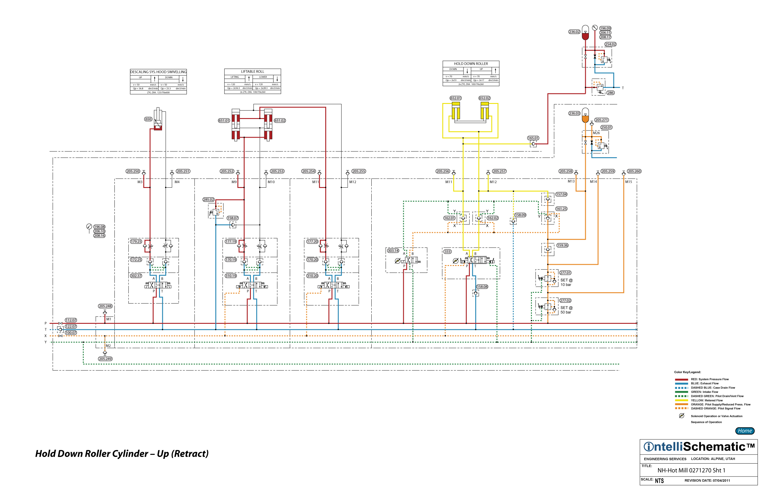
1) Directional Control Valve 303.14 is energized to the parallel flow pattern allowing pressurized hydraulic fluid to flow through the valve passing from P to B. Pilot pressure delivered by this valve pilots open Pilot Operated Check Valves 161.25, 162.01 and 162.02.
2) Proportional Directional Control Valve 333 is energized to the crossover flow pattern allowing pressurized hydraulic fluid to flow through the valve passing from P to B. The fluid then flows through Pilot Operated Check Valve 162.02 into the rod ends of Hold Down Roller Cylinders 652.01 and 652.02, causing the cylinders to retract. The proportional directional control valve controls the retraction speed of the cylinders via both meter-in and meter-out flow control.
3) Exhaust fluid from the cap ends of the cylinders flows freely through Pilot Operated Check Valve 162.01, which was piloted open in step 1, above, then through the proportional directional control valve, passing from A to T.
4) Finally, the exhaust fluid returns to tank after flowing through Check Valve 122.07 and Duplex Return Line Filter 045.01.
5) Note that Accumulator 236.03 is connected to the rod ends of the cylinders when Pilot Operated Check Valve 161.25 was piloted open in step 1. However, the pressure of the fluid in the accumulator is reduced to 10 bar by Proportional Pressure Reducing Valve 277.01. The pressure in the rod ends of the cylinders will be greater than 10 bar. Check Valve 157.04 prevents the higher pressure fluid from the rod ends of the cylinders from flowing to Accumulator 236.03. Therefore, the accumulator supplies no fluid to the rod ends of the cylinders during this event. This accumulator is used during Emergency Mode for this circuit. See the event “Hold Down Roller – Emergency Mode” for details on the use of this accumulator.
6) Accumulator 236.02 provides cushioning for the cap ends of the cylinders when external load forces act to retract the cylinders. Note that Check Valve 165.01 prevents any fluid which flows to this accumulator from flowing back into the cap ends of the cylinders. Pressure Relief Valve 286 relieves overpressure fluid to tank, protecting the accumulator and the cap ends of the cylinders from overpressure.