|
|
Liftable Roll Upper Cylinder - Lowering (Extend) |

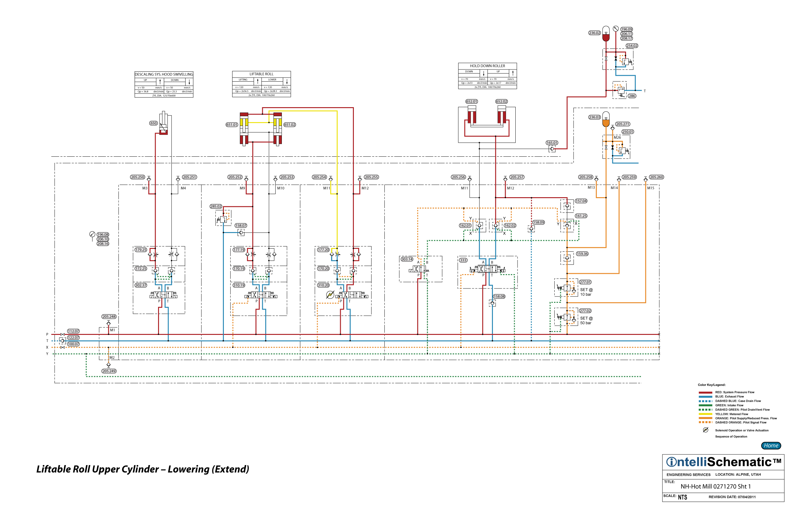
For previous sequences in this event see the event “Roll Change HPU – On.”
1) Directional Control Valve 310.20 is energized to the crossover flow pattern allowing pressurized hydraulic fluid to flow through the valve, passing from P to B. Next, the fluid flows freely through the B-port check valve of Dual Pilot Operated Check Valve Module 170.20 and the B-port check valve of Dual Flow Control Valve Module 177.20 and into the cap ends of the upper sections of Liftable Roll Cylinders 651.01 and 651.02 causing the upper ends of the cylinders to extend.
2) Exhaust fluid from the rod ends of the upper sections of the cylinders is forced by the A-port check valve of the flow control module to flow through the A-port needle valve of the module, thereby achieving meter-out speed control of the extension speed of the cylinders.
3) Next, the exhaust fluid flows through the A-port check valve of the pilot operated check valve module, which has been piloted open by pilot pressure from the B-side of the circuit.
4) Finally, the exhaust fluid flows through the directional control valve, passing from A to T, then back to tank through Check Valve 122.07 and Duplex Return Line Filter 045.01.