|
|
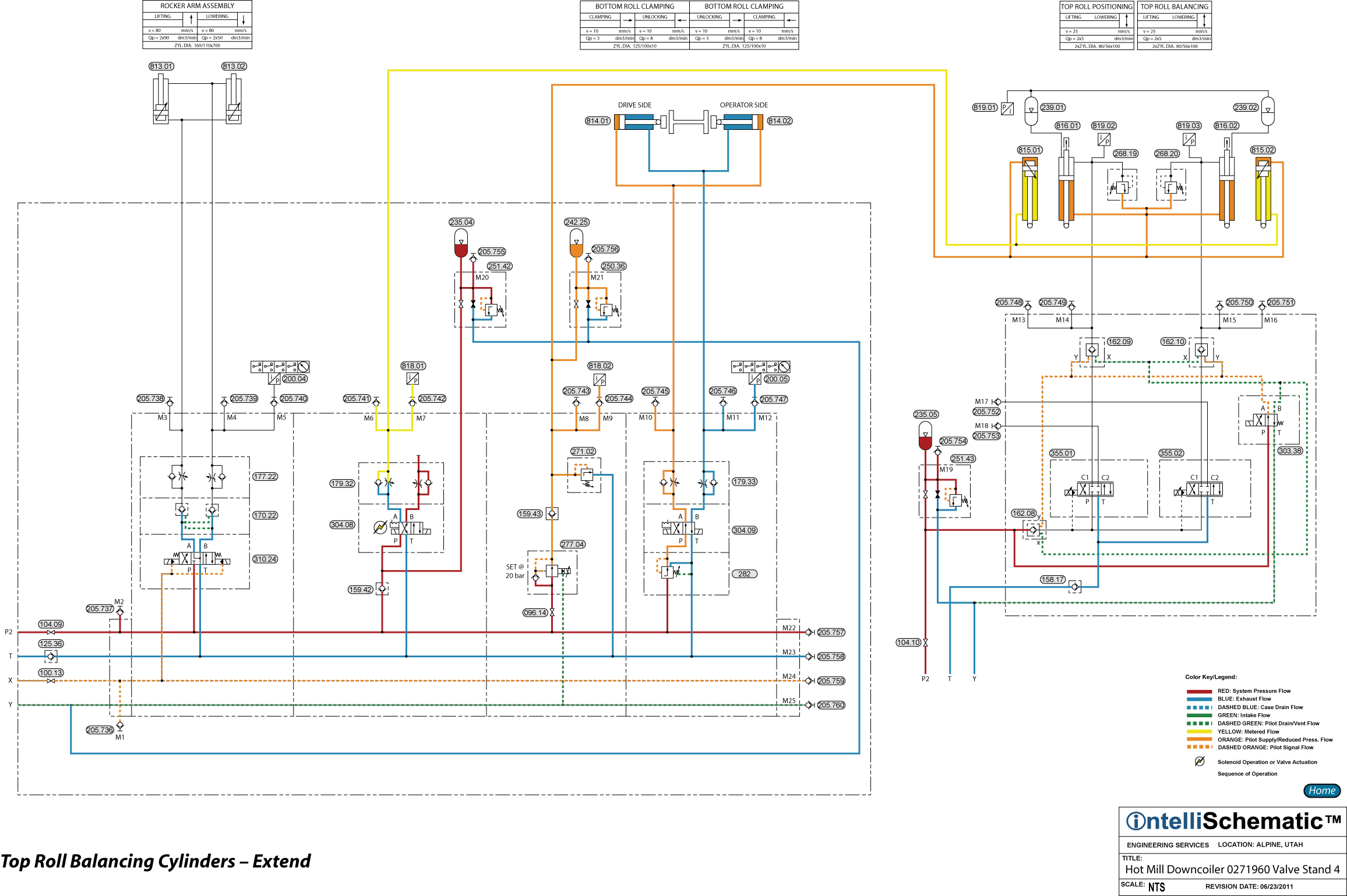
Top Roll Balancing Cylinders - Extend |

For previous steps in this sequence see the event “HPU – On.”
Note that the rod ends of Top Roll Balancing Cylinders 815.01 and 815.02 are pinned to the Upper Pinch Roll.
The cap ends of the balancing cylinders are constantly pressurized to 20 bar by pressurized hydraulic fluid controlled by Pressure Reducing-Relieving Valve 277.04. Check Valve 159.43 prevents pressurized fluid from flowing back towards the secondary (outlet) port of the pressure reducing valve. Pressure Relief Valve 271.02 protects the cap ends of the cylinders from overpressure. Accumulator 242.25 compensates for pressure and volume changes in the event of a sudden change in the cylinder stroke positions. The cylinder rod sides operate at a pressure of 210 bar.
1) Pressurized hydraulic fluid flows through Check Valve 159.42 to the P-port of Directional Control Valve 304.08 which is energized to the crossover flow pattern allowing the fluid to pass through the valve from P to B. The fluid then flows freely through the B-port check valve and deadheads at a blocked port.
2) Note that the cap ends of the balance cylinders are pressurized to 20 bar, thus creating a pressure differential when the rod ends of the cylinders are vented to tank through Directional Control Valve 304.08.
3) Since the valve spool in Directional Control Valve 304.08 also connects port A to tank (Port T), the rod ends of the balancing cylinders are vented to tank allowing the pressure in the cap ends to extend the cylinders. The flow rate of the exhaust fluid is controlled because the A-port check valve in the flow control module forces the vented exhaust fluid to be metered-out through the A-port needle valve. Thus, the extension speed of the cylinders is controlled.
4) Finally, after the exhaust fluid flows through the directional control valve, the fluid flows back to tank after flowing through Duplex Return Line Filter 045.03.