|
|
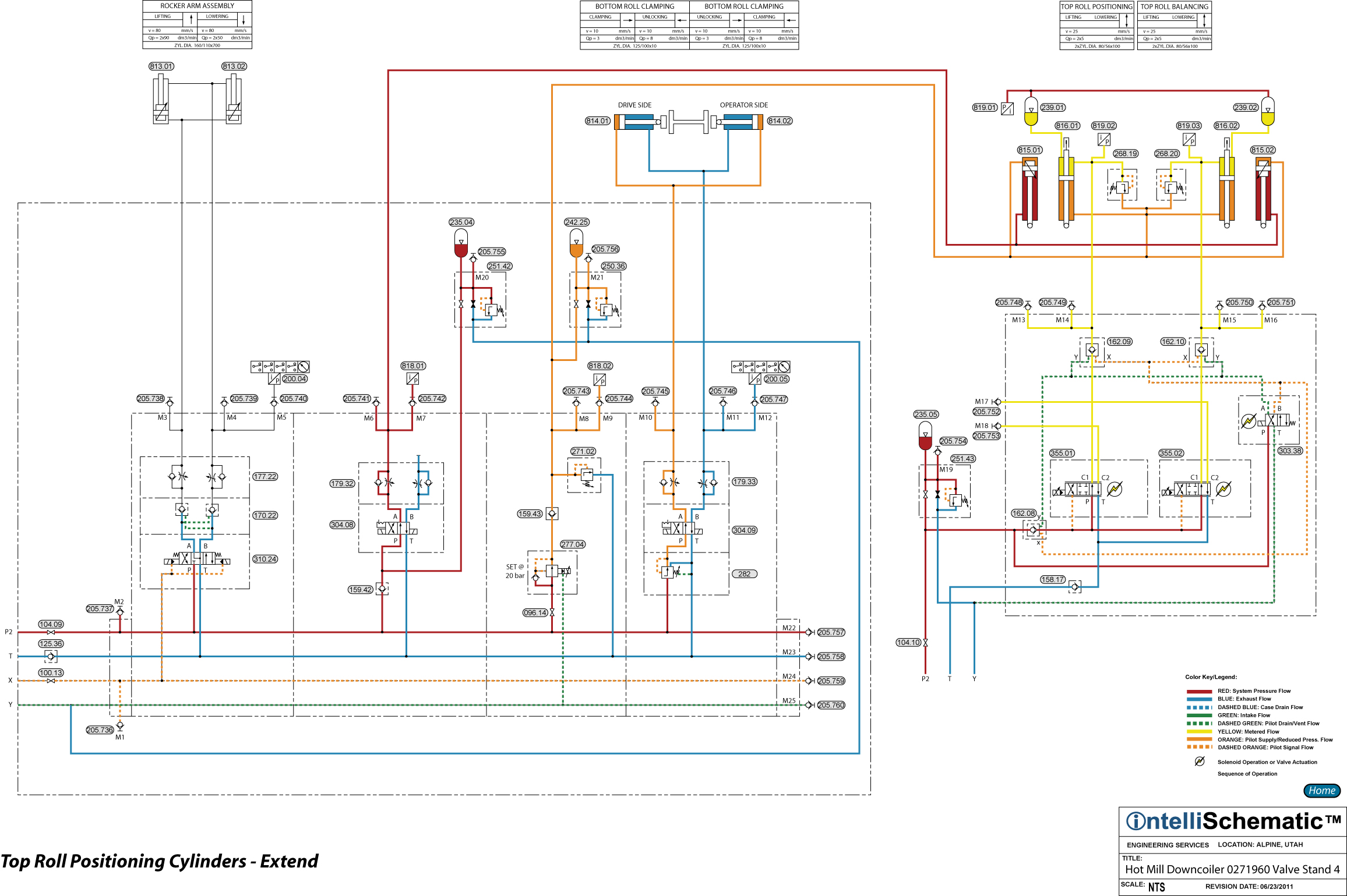
Top Roll Positioning Cylinders - Extend |

For previous steps in this sequence see the event “HPU – On.”
Notes:
A) Accumulator 235.05 provides instantaneous flow to supply Servo Valves 355.01 and 355.02 to compensate for the response time of the pressure compensators of the high pressure pumps that supply this circuit. The servo valves have much shorter response times than do pump compensators.
B) Accumulators 239.01 and 239.02 are connected to the cap ends of Top Roll Positioning Cylinders 816.01 and 816.02 and are installed to cushion pressure surges as the cylinder stroke changes. The gas pressure in the accumulators is monitored by Pressure Transducer 819.01. The stroke positions of the cylinders are monitored by position transducers.
C) The position of Top Roll Positioning Cylinder 816.01 is controlled Servo Valve 355.01 and the position of Top Roll Positioning Cylinder 816.02 is controlled Servo Valve 355.02. The event description will discuss only cylinder 816.01, but the same sequence applies for 816.02.
D) The rod ends of the positioning cylinders are constantly pressurized to 20 bar by pressurized hydraulic fluid controlled by Pressure Reducing-Relieving Valve 277.04. Check Valve 159.43 prevents pressurized fluid from flowing back towards the secondary (outlet) port of the pressure reducing valve. Pressure Relief Valve 271.02 protects the cap ends of the cylinders from overpressure. Accumulator 242.25 compensates for pressure and volume changes in the event of a sudden change in the cylinder stroke positions. The cap ends of the cylinders operate at 210 bar.
1) Directional Control Valve 303.38 is energized to the crossover flow pattern delivering pilot pressure to open Pilot Operated Check Valves 162.08, 162.09 and 162.10 while venting the drain ports of those check valves. With these check valves piloted open, pressurized hydraulic fluid may flow to the P-port of Servo Valves 335.01 and 335.02. Also, the C1 port of each servo valve is then connected to the cap end of their respective positioning cylinder.
2) Servo Valve 355.01 is energized to the parallel flow pattern allowing pressurized hydraulic fluid to flow through the servo valve, passing from P to C1, metering hydraulic fluid into the cap end of Top Roll Positioning Cylinder 816.01, causing the cylinder to extend.
3) Exhaust fluid from the rod end of the positioning cylinder may flow back to tank by relieving through Pressure Relief Valve 271.02. Small volumes of exhaust fluid may simply be absorbed by Accumulator 242.25.