|
|
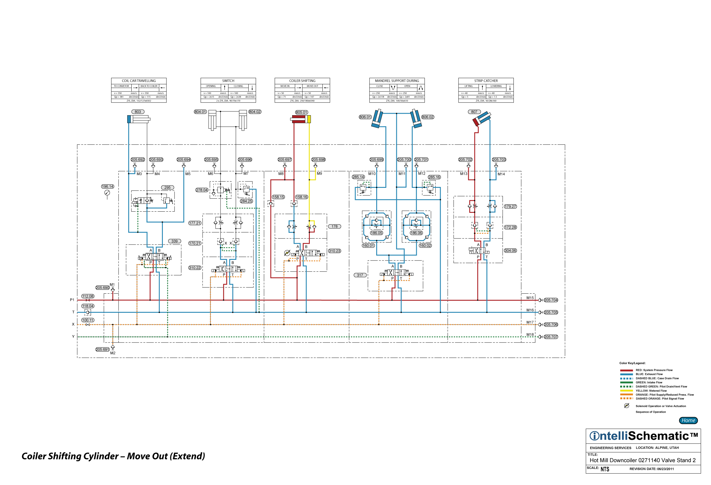
Coiler Shifting Cylinder - Move Out (Extend) |

For previous steps in this sequence see the event “HPU – On.”
1) Directional Control Valve 310.23 is energized to the crossover flow pattern allowing pressurized hydraulic fluid to pass through the valve from P to B, then through Flow Control Valve Module 178 and into the cap end of Coiler Shifting Cylinder 805 causing the cylinder to extend. Note that the B-port check valve in the flow control valve module forces the fluid to flow through the B-port needle valve of the module, thereby achieving meter-in speed control of the extension speed of the cylinder.
2) Exhaust fluid from the rod end of the cylinder is blocked from flowing to the directional control valve and then back to tank by Check Valve 158.16. Instead, the exhaust fluid flows through Check Valve 158.15 and then back to the pressure line supplying the P-port of the directional control valve. Thus, the rod end fluid flows through the directional control valve, passing from P to B, and then into the cap end of the cylinder, allowing the cylinder to extend at a faster speed than if the exhaust flow was directed back to tank.
3) This valve arrangement is one way of plumbing a regen, or regenerative, circuit, which is used to increase the extension speed of a cylinder. The pressure intensification in the rod end of the cylinder, which is a result of the differential areas of the cylinder, provides the pressure differential (there is higher pressure in the rod end of the cylinder than in the cap end) to allow the exhaust fluid to flow through Check Valve 158.15.