|
|
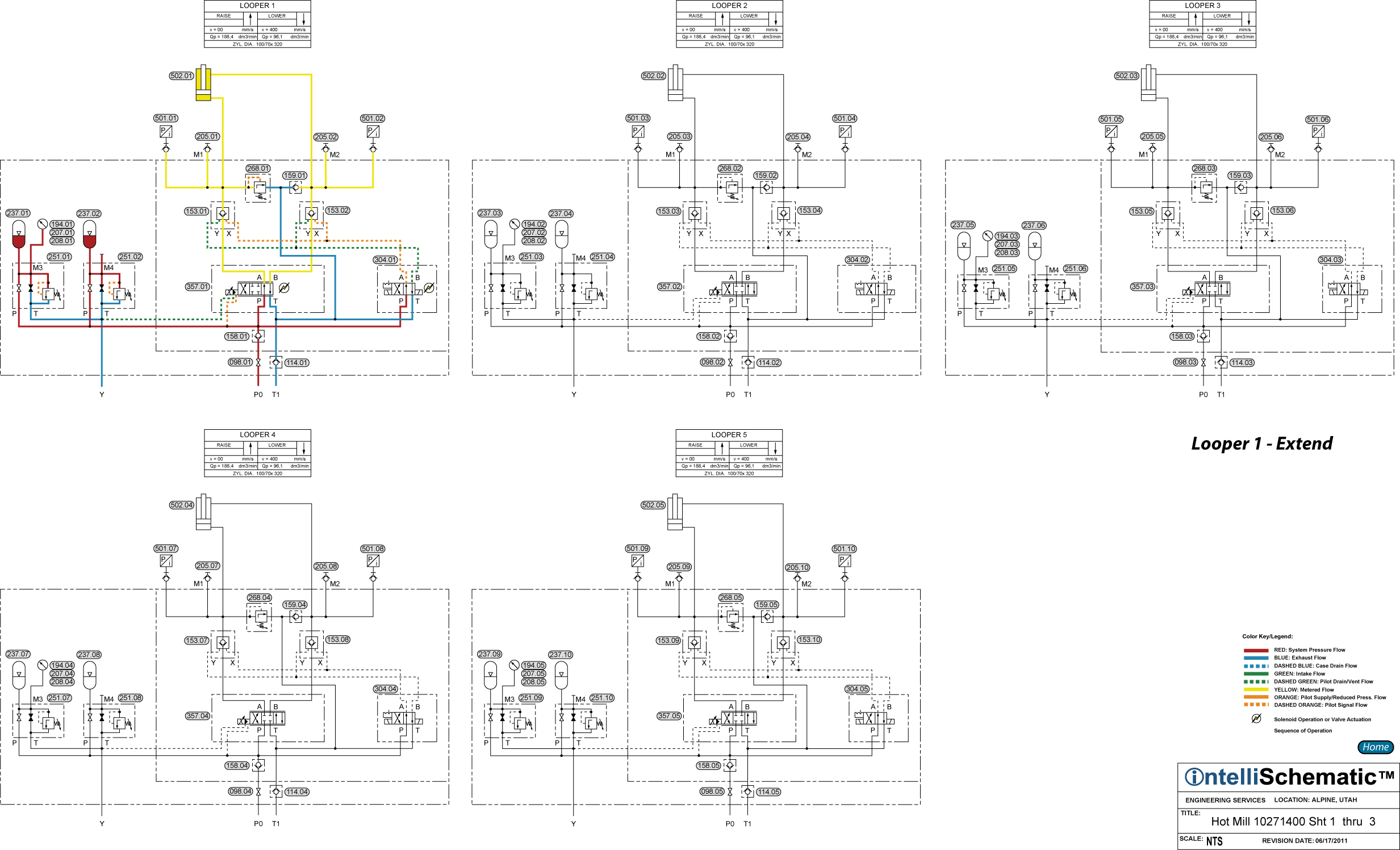
Looper 1 - Extend |

See the event “HPU – On” FOR previous steps in this sequence.
Note that this event describes the sequences for Looper 1. The same sequences apply for Loopers 1 through 5, though the component numbers will change. Refer to the relevant schematic for each stand for the appropriate component number.
1) Pressurized hydraulic fluid flows through Check Valve 158.01 to Accumulators 237.01 and 237.02 and the P-ports of Directional Control Valve 304.01 and Proportional Directional Control Valve 357.01.
2) Simultaneously, Directional Control Valve 304.01 and Proportional Directional Control Valve 357.01 are energized to the parallel flow positions. Directional Control Valve 304.01 delivers pilot pressure to Pilot Operated Check Valves 153.01 and 153.02, piloting the check valves open.
3) Pressurized fluid flows through the proportional directional control valve, passing from P to A, then through Pilot Operated Check Valve 153.01 into the cap end of Looper 1 cylinder 502.01, causing the cylinder to extend. Pressure Relief Valve 288.01 protects the cap end of the cylinder from overpressure. Check Valve 159.01 allows relieved fluid to flow into the rod end of the cylinder in order to prevent cavitation at the rod end.
4) Exhaust fluid from the rod end of the cylinder flows freely through Pilot Operated Check Valve 153.02, then through the proportional directional control valve, passing from B to T. Note that the proportional directional control valve meters the fluid flowing both to and from the cylinder.
5) The two accumulators supply pressurized fluid during short periods of low pressure in the main pressure header line, caused by momentary flow demands in other parts of the system. Check Valve 158.01 prevents pressurized fluid delivered by the accumulators from flowing back into the main pressure header line. In addition, in the event of a power failure, the proportional directional control valve assumes “position a,” so the looper is lowered below the passline. The accumulators provide pressurized fluid for the lowering of the looper. The accumulators also provide flow when for very fast movements of the looper during startup.
6) The looper runs in both position and pressure control. Rotational speed correction signals for the mill stands are derived from the position of the loopers during rolling.
7) When Directional Control Valve 304.01 is energized to the crossover flow pattern, Pilot Operated Check Valves 153.01 and 153.02 are closed, preventing the position of the looper cylinder from being controlled by Proportional Directional Control Valve 357.01. Note that Directional Control Valve 304.01 has detented switching positions, so the active position is retained in the event of an electrical power loss.