|
|
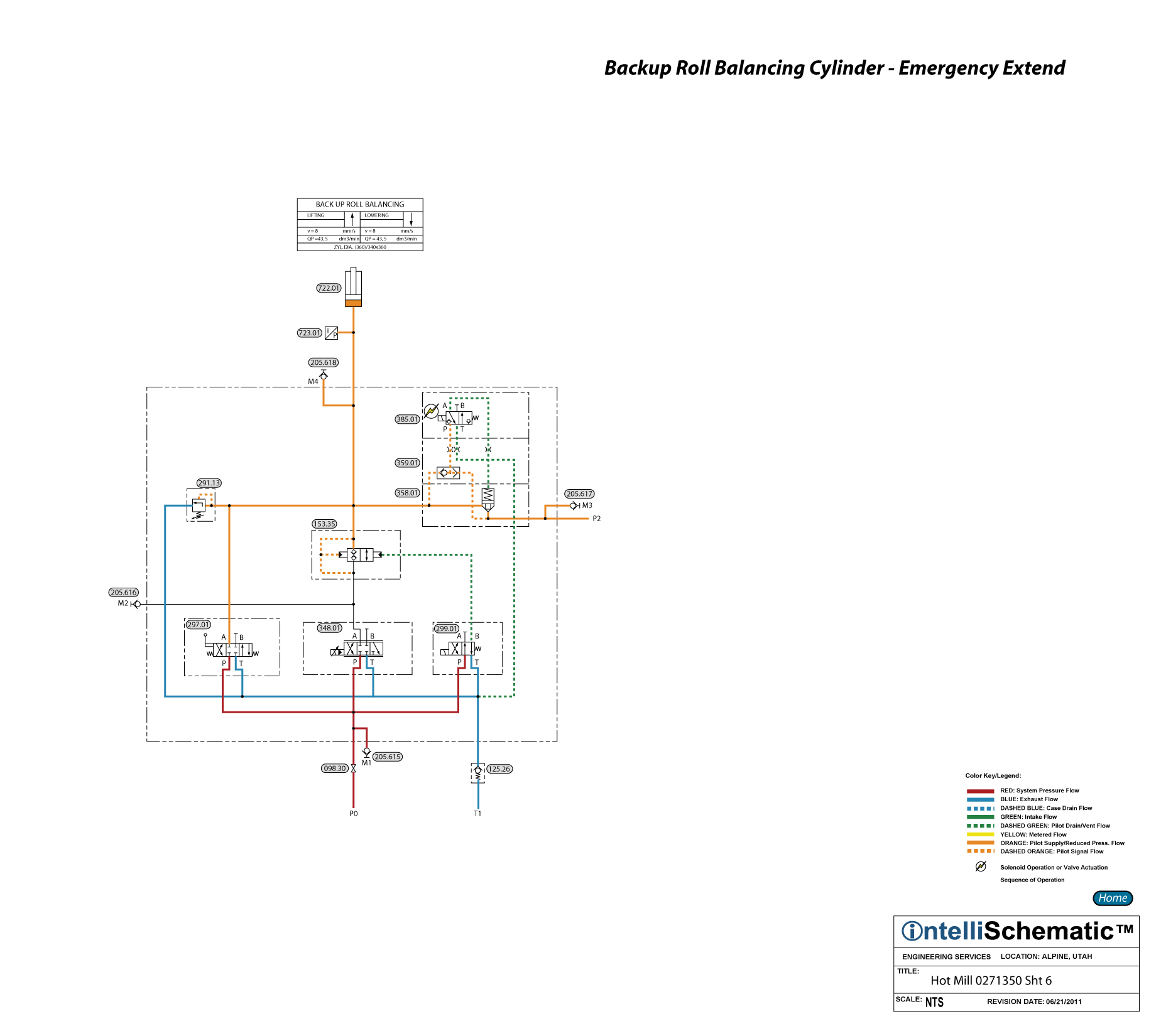
Backup Roll Balancing Cylinder - Emergency Extend |

See the event “HPU – On” for previous steps in this sequence.
Note that this event describes the sequences for Mill Stand F1. The same sequences apply for stand F2 through F6, though the component numbers will change. Refer to the relevant schematic for each stand for the appropriate component number.
1) In an emergency, Pilot Operated Check Valve 153.35 is closed by de-energizing Directional Control Valve 299.01.
2) Simultaneously, the connection to the Piston Accumulator 244 is opened by energizing Directional Control Valve 285.01 which vents the spring chamber of DIN Cartridge Valve Insert 358.01, allowing the valve insert to open, allowing pressurized hydraulic fluid to flow from the accumulator into the cap end of Back Up Roll Balancing Cylinder 722.01, causing the cylinder to extend.
3) Pressure Relief Valve 291.13 protects the cap end of the cylinder from overpressure.