|
|
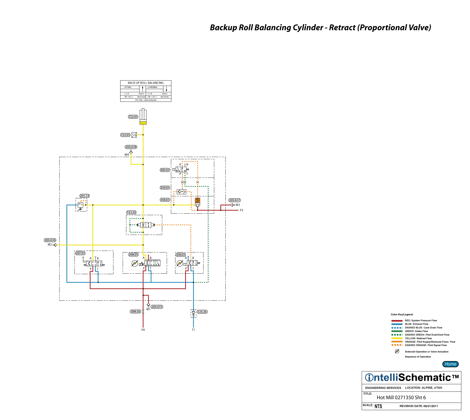
Backup Roll Balancing Cylinder - Retract (Proportional Valve) |

See the event “HPU – On” for previous steps in this sequence.
Note that this event describes the sequences for Mill Stand F1. The same sequences apply for stand F2 through F6, though the component numbers will change. Refer to the relevant schematic for each stand for the appropriate component number.
1) Directional Control Valve 299.01 is energized to the crossover flow pattern, piloting Pilot Operated Check Valve 153.35 open, allowing hydraulic fluid to flow freely in either direction through the check valve.
2) Simultaneously, Proportional Pilot Operated Directional Control Valve is energized to the crossover flow pattern, metering exhaust hydraulic fluid from the cap end of Back Up Roll Balancing Cylinder 722.01, allowing the cylinder to retract.
3) Pilot pressure flows through the shuttle valve in DIN Cartridge Valve Cover 259.01 into the spring chamber of DIN Cartridge Valve Insert 258.01, piloting the valve insert closed.
4) Pressure Relief Valve 291.13 protects the cap end of the cylinder from overpressure.