|
|
Bending-Balancing Cylinders - Emergency Balancing |

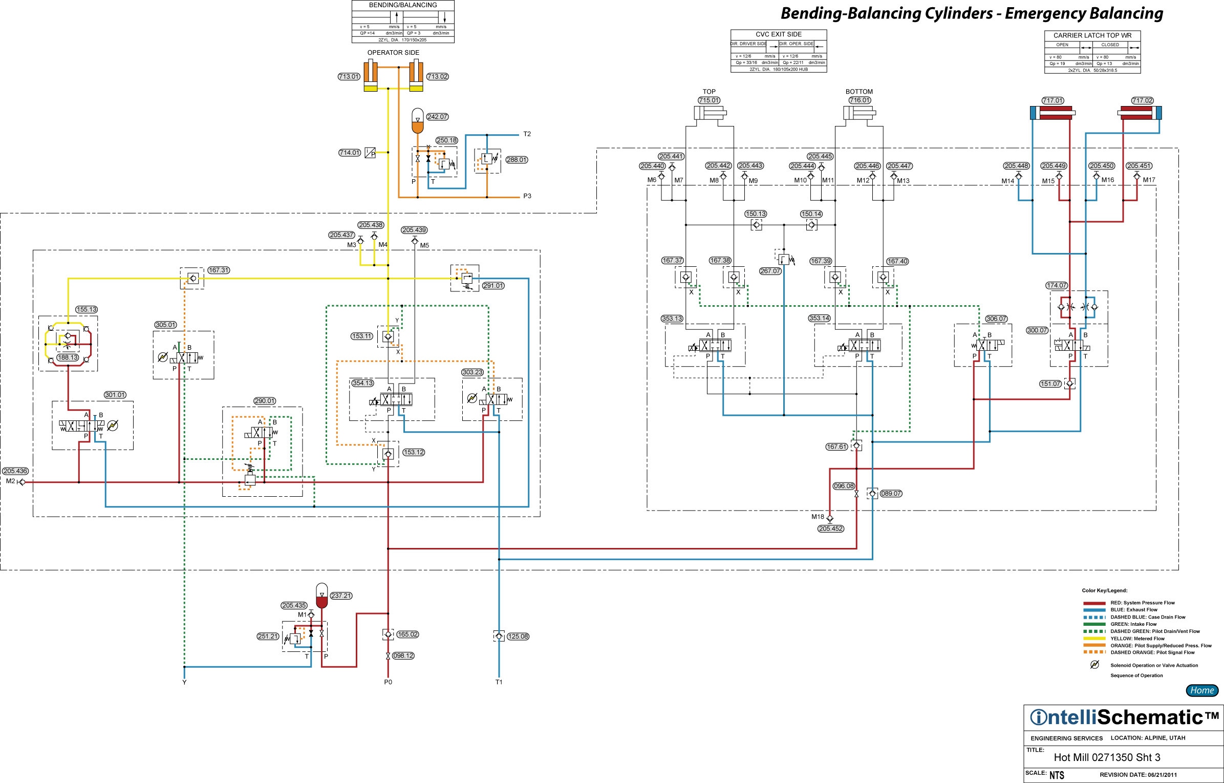
Bending-Balancing Operator Side Cylinders – Emergency Balancing
See the event “HPU – On” for previous steps in this sequence.
Note that this event describes the sequences for Mill Stand F1. Also, this event describes the sequences for the Drive Side cylinder circuits. The same sequences apply for stand F2 through F6, though the component numbers will change. Refer to the relevant schematic for each stand for the appropriate component number.
Servo Valve 354.13 is normally used to control the work roll balancing pressure when rolling steel. However, the servo valve can be taken out of operation in an emergency by the following operation:
1) ) The Bending-Balancing Accumulator Stand supplies pressurized hydraulic fluid to Accumulator 242.07 via Pressure Header Line P3, keeping the rod ends of Operator Side Bending-Balancing Cylinders 713.01 and 713.02 pressurized at all times.
2) Pressurized hydraulic fluid flowing to Directional Control Valve is reduced in pressure by Pressure Reducing Valve 290.01. The pressure setting of this pressure reducing valve may be set at either 1750 psi (de-energized – rolling strip) or 860 psi (energized – roll changing).
3) Directional Control Valve 305.01 is energized to the crossover flow pattern, delivering pilot pressure to Pilot Operated Check Valve 167.31 to pilot the valve open.
4) Directional Control Valve 301.01 is energized to the parallel flow pattern allowing reduced pressure hydraulic fluid to flow through the valve, passing from P to A.
5) Next, the fluid flows though Rectifier Plate 155.13 and Pressure Compensated Flow Control Valve 188.13. The check valves in the rectifier plate cause the hydraulic fluid to always flow through the flow control valve in the correct direction (from right to left in the schematic) to provide identical speeds extending and retracting the Bending-Balancing Cylinders. Using compass directions, the incoming fluid flows freely through the SE check valve but is blocked by the SW and NE check valves, directing the fluid to the right side of the flow control valve symbol. The check valve in the flow control forces the hydraulic fluid through the adjustable metering orifice in the flow control valve. The metered fluid then flows freely through the NW check valve and then out of the rectifier plate. Pressure differential caused by pressure drop across the flow control valve prevents the metered fluid from flowing through the NE and SW check valves.
6) Then the fluid flows freely through Pilot Operated Check Valve 167.31 then into the cap ends of Bending-Balancing Operator Side Cylinders 713.01 and 713.02 causing the cylinders to extend.
7) Exhaust fluid from the rod ends of the cylinders flows into the P3 header line. Pressure Reducing-Relieving Valve 280.03 will act to relieve overpressure fluid to tank. Accumulator 242.07 provides cushioning at the rod ends of the cylinders.
8) Pilot Operated Check Valve 153.11, which is vented closed as Directional Control Valve 303.23 is de-energized, prevents pressurized hydraulic fluid from flowing toward the A-port of Servo Valve 354.13. Pressure Relief Valve 291.01 protects the cap ends of the cylinders from overpressure.