|
|
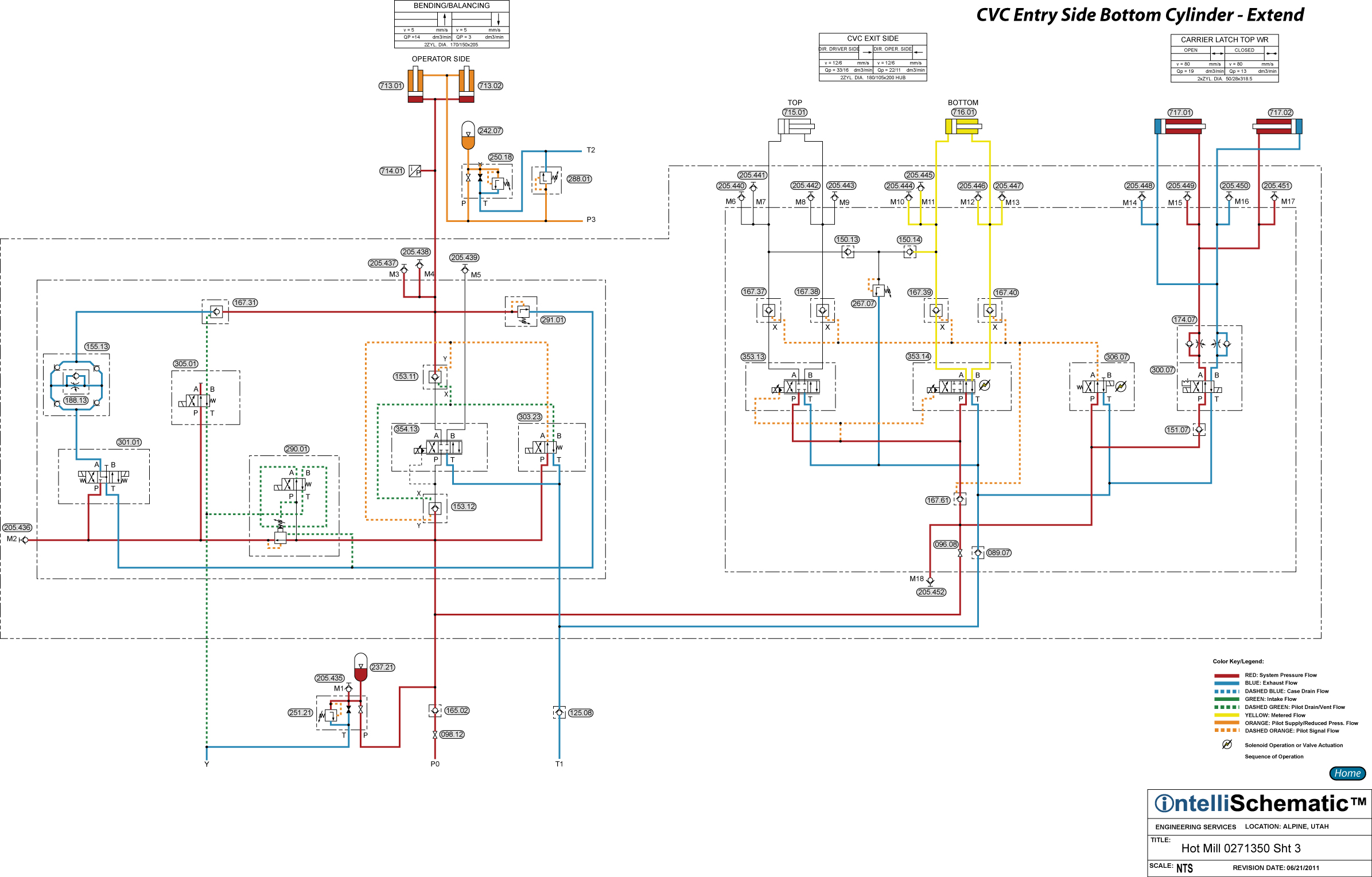
CVC Entry Side Bottom Cylinder - Extend |

See the event “HPU – On” for previous steps in this sequence.
Note that this event describes the sequences for Mill Stand F1. Also, this event describes the sequences for the CVC Exit Side Bottom cylinder circuit. The same sequences apply for stand F2 through F6, though the component numbers will change. Refer to the relevant schematic for each stand for the appropriate component number.
1) Directional Control Valve 306.01 is energized to the parallel flow pattern directing pilot pressure to the X-ports (pilot pressure ports) of Pilot Operated Check Valves 167.01 through 167.05, opening these five check valves.
2) Simultaneously, Servo Valve 353.02 is energized to the parallel flow pattern. Pressurized hydraulic fluid flows through Pilot Operated Check Valve 167.05 to the P-port of the servo valve, passing through the servo valve from P to A before flowing through Pilot Operated Check Valve 167.03 into the cap end of CVC Entry Side Bottom Cylinder 711.01, causing the cylinder to extend.
3) Exhaust fluid from the rod end of the cylinder flows freely through Pilot Operated Check Valve 167.04, then through the servo valve, passing from B to T.
4) Finally, the exhaust fluid flows back to tank through Check Valve 089.01 and Duplex Return Line Filter 045.02.
5) Note that due to the metering type of spool in the servo valve, hydraulic fluid is metered both to the cap end and from the rod end of the cylinder.