|
|
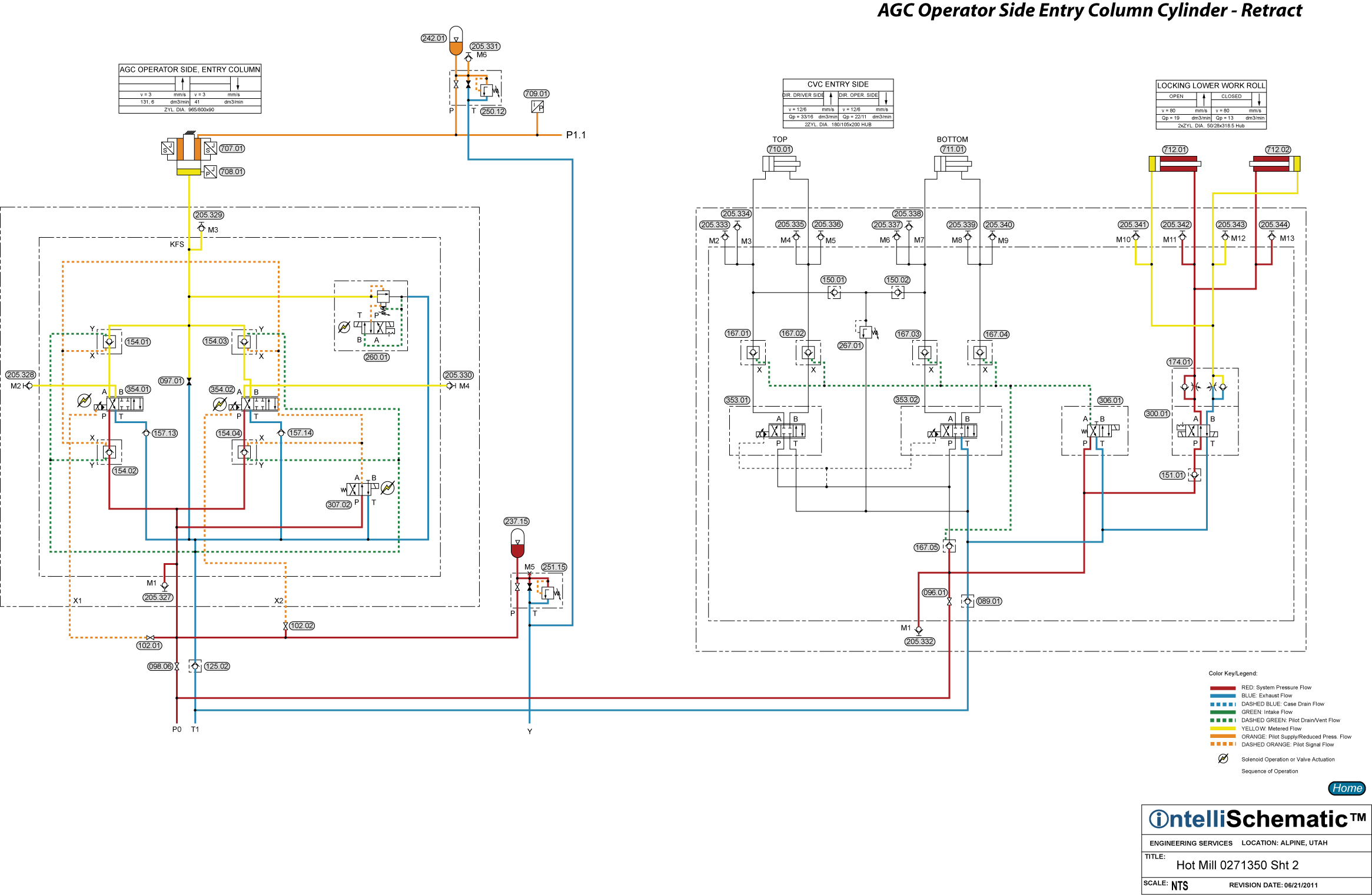
AGC Operator Side Entry Column Cylinder - Retract |

See the event “HPU – On” for previous steps in this sequence.
Note that this event describes the sequences for Mill Stand F1. Also, this event describes the sequences for the AGC Drive Exit Column cylinder circuit. The same sequences apply for stand F2 through F6, though the component numbers will change. Refer to the relevant schematic for each stand for the appropriate component number.
1) Note that the rod end of AGC Operator Side Entry Column Cylinder 707.01 is connected to Accumulator 242.01, which in turn is connected to the AGC Accumulator Stand. This accumulator stand operates at two different pressures, delivering 60 bar for retracting pressure during roll changes and at 25 bar for retracting pressure during the rolling of steel. See the events “AGC Accumulator Stand Delivering Low Pressure” and “AGC Accumulator Stand Delivering High Pressure” to see how the change in the supplied pressure is made.
2) Directional Control Valve 307.02 is energized to the parallel flow pattern delivering pilot pressure to the pilot pressure ports of Pilot Operated Check Valves 154.01, 154.02, 154.03 and 154.04 allowing pressurized hydraulic fluid to flow to the pressure ports of Servo Valves 354.01 and 354.02. Also, the A-port of 354.01 and the B-port of 354.02 are now open to the cap end of AGC Operator Side Entry Column Cylinder 707.01. Therefore, the servo valves are not isolated from the incoming hydraulic supply and from the cylinder.
3) In normal operation the two servo valves operate as a cumulative system. In other words, up to a predetermined signal value, only one servo valve is energized to deliver flow to the cylinder. At that threshold point, the second servo valve is energized and the flow rate to or from (depending on whether the cylinder is being extended or retracted) the cylinder continues to increase.
4) To retract the cylinder, Servo Valves 354.01 and 354.02 are actuated to the crossover flow pattern, allowing exhaust fluid to flow from the cap end of the cylinder through the servo valves, then back to tank through Check Valve 125.02 and Duplex Return Line Filter 045.02. The servo valves control the retraction speed of the cylinder.
5) Pressure Relief Valve 260.01 is normally energized to its high pressure setting (the parallel flow pattern on the solenoid valve), though for maintenance purposes, it may be energized to low pressure (the crossover flow pattern on the solenoid valve). This pressure relief valve protects the cap end of the cylinder from overpressure.
6) Accumulator 237.15 provides instantaneous flow to the servo valves to compensate between the flow demand of the servo valves and the compensator response time of Pressure Compensated Pumps 006.01 through 006.07.Accumulator 242.01 provides cushioning for the rod end of the cylinder.